Only one link today: https://github.com/OSGP-Alliance-MEP-and-Optical.
Not there yet – but pretty close now 🙂
…dabbling to the ++level
Misc. software stuff

Only one link today: https://github.com/OSGP-Alliance-MEP-and-Optical.
Not there yet – but pretty close now 🙂
Our software fix for the (fake?) MAX3232 hardware issue seems to solve the issue completely.
It is still a rough implementation in the software (using delays), so we’ll have to improve on that later on… It is probably not that big of an issue – because when a MAX3232 starts to behave, it seems it continue that way for a long time…
Next step is then off cause a new hardware prototype PCB, but why not add a few things like:
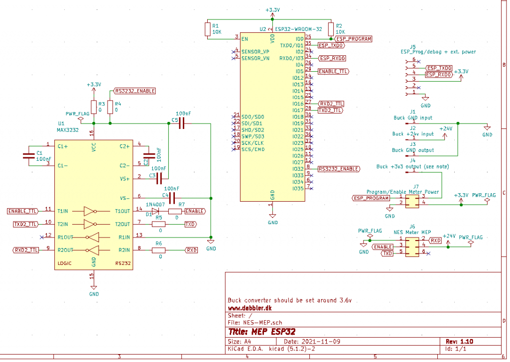
The schematics now looks like this:
A 3D rendering of the PCB (for some reason without a 3D MAX3232) looks like this:
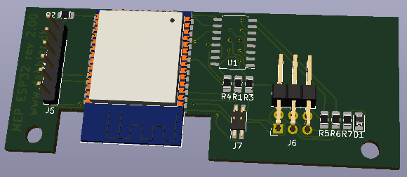
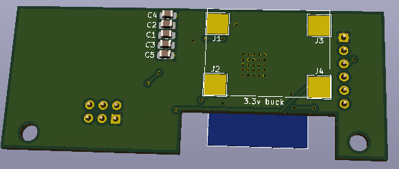
The idea around putting C1 – C5 on the back is to shorten the traces from the MAX3232 (supposedly that is also better according to it’s datasheet… But what do we know – we are software guys 🙂 )
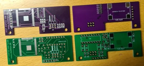
We’ve just received the PCBs from JLC PCB (no, they are not a sponsor – we pay for this), but have not had time to populate nor test them yet…
You can see the received PCBs in the feature image of this blog entry.
Stay tuned for more news regarding this project – only on www.dabbler.dk…
Note: We are still waiting for NES to release the MEP protocol specifications…
Well, we warned you that software guys like us tend to come up with software solutions – even for hardware problems.
As expected, no electronic engineers reached out to us with a solution for our (probably fake) MAX3232 issues, so we had to come up with a solution ourselves…
That is off cause ok – and with the help of a cut PCB trace:
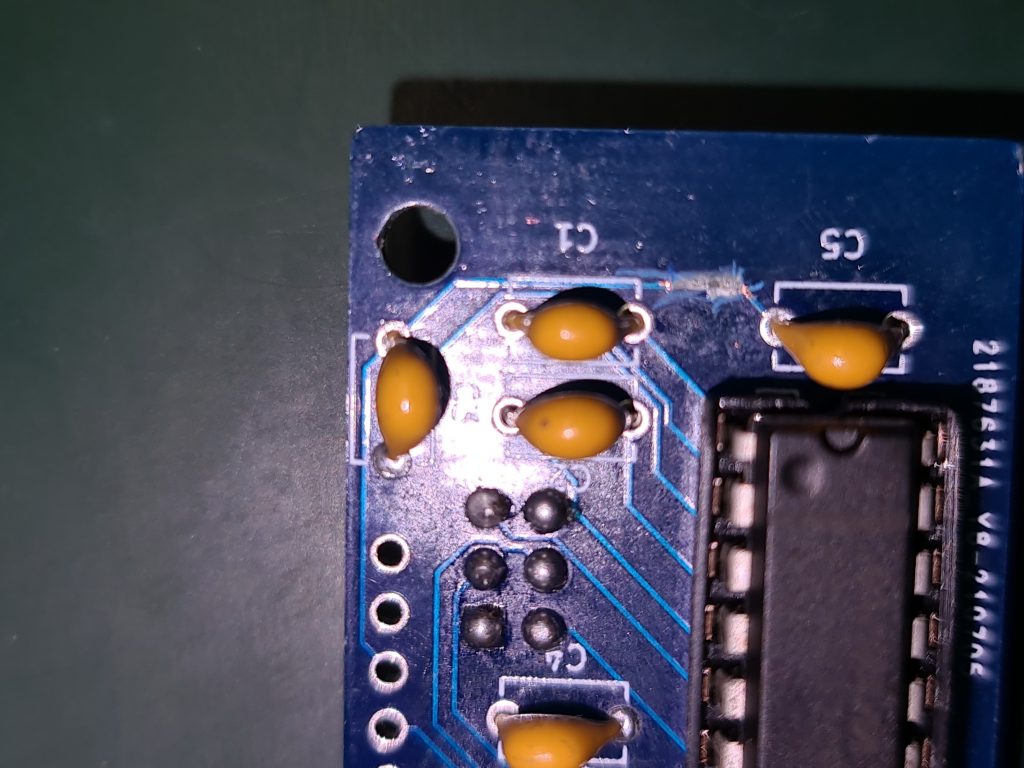
… and a bodge wire:
… it seems we can persuade the MAX3232’s to play along.
This is off cause a temporary solution to test this fix – we need a new PCB prototype version if this works.
Note: You will find others struggling with similar MAX232/3232 issues on the Internet. Some are able to solve it with larger decoupling capacitors and some with resisters on the power pin – but that did not work for us.
Our implementation is simply adding control of the power to the MAX3232 through software. When it mis-behaves we punish it by turning it off for a while. Then back on until it behaves…
Note: the max current a ESP32 digital pin can supply seems to be around 40mA and the max consumption of a MAX3232 is around 1mA. So we should be safe doing this “hack”…
If you are an electronic engineer you are probably finding this solution fun – but it seems to be working :-).
While we are still waiting for the MEP Protocol specification to be released (and our NDA to be lifted), we’ll try to keep your entertained with more blog entries.
Stay tuned to www.dabbler.dk…

This is another bonus entry on our blog in the Echelon/NES Smart Meters series. As we have mentioned before, it is sometimes hard to find time besides our regular jobs to dabble with this project. We have had a lot of interest in using the IR (Infrared) port on the Echelon/NES Smart Meters, and there have been (at least with N1) some confusion about if it was encrypted or not.
We know that someone at Sommerhack 2021 had been told by N1 that they should be able to use the IR port and that the key was the same as the MBK used for the MEP communication. We have not tried that ourselves as we have chosen to focus our limited time on the MEP integration. And to our knowledge – nobody else have tried the IR approach – that is – until now :-).
Our fellow tinkere Ulrik was faced with the challenge that his power supplying company Konstant, does not allow him to use the MEP-port on his Echelon meter. They are simply following another approach compared to N1, and suggests that their customers should use the IR-port.
Overall/political speaking this is actually really good news. Because if N1 can allow us to use the MEP port in a safe way, why should Konstant be against it for security reasons? Why should they not agree to allow it sometime in the future if they are pushed?
Also – if Konstant can allow their customers to use the IR port in a safe way, why should N1 be against it for security reasons? Why should they not agree to allow it sometime in the future (if not already?) if we push them?
Some have been dreaming of being able to interface with the Echelon/NES meters for years – but it was not possible due to a lot of “red tape”. Maybe we now have or will get TWO separate interfaces for interfacing with Echelon/NES Meters?
Enough dabbling with words from dabbler.dk – let’s hand over this scene to Ulrik and let us hear what he was actually able to do with the IR port:
First of all, I would like to say thank (and sorry) to Gert and Graves for letting me ‘spam’ them with my thoughts, questions and discoveries. And of cause for helping me out from time to time :-).
INFO:
My name is Ulrik and I work as an Automation technician. I started out as an electrician and was fascinated by all the technical stuff you could do. I have around 30 Years of technical background. I build my own house in year 2000 where I put in a PLC to control the house. All lightning, heating, ventilation and alarmsystem is run from that.
Well… Back on the track… I started out collecting the pulses from my main meter by using the S0 pulses. Worked great, until I got solarpanels installed and the meter now send out pulses whenever a watt was produced or consumed, so not that usefull :-(. Then I started looking at other ways and stumbled over a lot of options, among this was the IR port. So here’s a story of how I got this to work :-).
I have a NES 83334 meter. I also use Home Assistant.
I have very little knowledge of Python and NODE RED, so ‘Google was my friend’ 🙂
I also know that this setup could be much more ‘smart’. But for now, it just might get people started to get data from the meters 😉
My supply area is KONSTANT and they will send you the decryptkey if you contact them at info@konstant.dk
They also send me a draft version of Optical Port Programmer’s Guide with some info tables in the meter.
KONSTANT also told me that the meters they are using (ECHELON / NES) have the MEP port disabled, so I was unable to use that. So I went the optical IR eye way…
Communication parameter that I use:
9600, 8, 1, none
LINKS:
Install a RAM disk (to prevent destroying the SD card.)
https://www.hellojona.com/2017/06/create-a-ram-disk-tmpfs-in-raspberry-pi-3/
ANSI C1218 protocol description:
https://kupdf.net/download/ansi-c1218_598ceccadc0d606c4b300d1a_pdf
ANSI C1219 Protocol description:
https://kupdf.net/download/ansi-c12-19-2008_5af9fdd5e2b6f501147de395_pdf
Open Smart Grid Protocol (OSGP)
https://www.etsi.org/deliver/etsi_gs/osg/001_099/001/01.01.01_60/gs_osg001v010101p.pdf
Termineter (Framework for reading data from smartmeters)
https://github.com/rsmusllp/termineter
HARDWARE USED:
IR Probe:
I bought mine from Weidmann Elektronik
https://www.weidmann-elektronik.de/Produkt_IR-Kopf.html
1.00 x IR Schreib/Lesekopf USB (Optokopf), ART0027, EUR 44,99
I have not tried other probes, but I figured at the start of this project, I did not want to have trouble with my hardware. I know it’s kind of expensive but it works 🙂
Raspberry Pi 3 model B+ with 8 gb SD card:
(I used Raspberry Pi Imager and installed Raspberry Pi OS)
Activate VNC and SSH (Raspberry PI configuration – Interfaces)
SOFTWARE:
Install SAMBA
sudo apt install samba samba-common-bin
Edit the config file:
sudo nano /etc/samba/smb.conf

[pi]
path=home/pi
read only = no
writeable = yes
browseable = yes
guest ok = yes
create mask = 0755
directory mask = 0755

Press CTRL-o and CTRL-x to save and exit
Install a RAM disk (to prevent destroying the SD card.)
Link: https://www.hellojona.com/2017/06/create-a-ram-disk-tmpfs-in-raspberry-pi-3/
mkdir /var/tmp
Edit the fstab file.
sudo nano /etc/fstab
Add the following line to /etc/fstab to create a 400MB RAM Disk
tmpfs /var/tmp tmpfs nodev,nosuid,size=400M 0 0
Execute the following command to mount the newly created RAM Disk
mount -a
To verify the RAM Disk is created and mounted successfully, execute the following command
df -h
Temporary files can now be written/read to/from /var/tmp partition.
PYTHON 3.9 (I think that it is installed on the Raspberry by default).
Install NODE-RED
I think I installed it from the Rasberry Pi ‘recommended software’ via the GUI.
Autostart Nodered: (run from a terminal / SSH)
sudo systemctl enable nodered.service
Install Temineter (Python program to communicate C1218 and C1219 protocol)
Start a terminal and install it.
git clone https://github.com/securestate/termineter.git
Change permissions on directory
sudo chmod 777 termineter -R
I edited a some of files (I use Visual Studio Code through the SAMBA share) to get this to work.
You can use the files from the attached zip of use them as inspiration to copy/waste.
Changed files:
lib/c1228/connection.py
lib/termineter/core.py
lib/termineter/modules/get_data.py
lib/termineter/modules/read_part.py
TERMINETER program changes
lib\termineter\core.py:
*** Section around ‘Setup end configure options’
self.options.add_string('SERIAL_CONNECTION', 'serial connection string',default='/dev/ttyUSB0')
self.options.add_string('PASSWORD', 'serial c12.18 password', default='<your decryptkey here!>')
self.advanced_options.add_integer('C1218_PACKET_SIZE', 'c12.18 maximum packet size', default=64)
Run the program:
python ./termineter

Termineter
 <[ termineter v1.0.5
 <[ model: T-1000
 <[ loaded modules: 19

termineter >
Run the module to start getting data:
termineter > run get_data
Hopefully the program starte to get data (and save it in the /var/tmp folder)
[+] Successfully connected and the device is responding
[*] Read 8 bytes
0000 74 40 05 00 9f 1d 00 00                         t@......
[*] Read 40 bytes
0000 96 0a 00 00 00 00 00 00 00 00 00 00 39 02 00 00 ............9...
0010 f8 0c 00 00 dc 0c 00 00 90 19 00 00 27 70 03 00 ............'p..
0020 ef 6f 03 00 76 70 03 00                         .o..vp..
Instead of (or additional) to make the program changes, you can use a ‘resource file’ (look at
https://github.com/rsmusllp/termineter/wiki/GettingStarted at the bottom)
If you use a resource file, you can ‘autostart’ the program.
Errorhandling still needs to be taken care of 😉
NODE-RED Program:
The data from termineter is stored in /var/tmp BT23 and BT28 and is updated every 10 sec-ish.
I use NODE-RED to handle the data (and send them to HomeAssistant via MQTT)
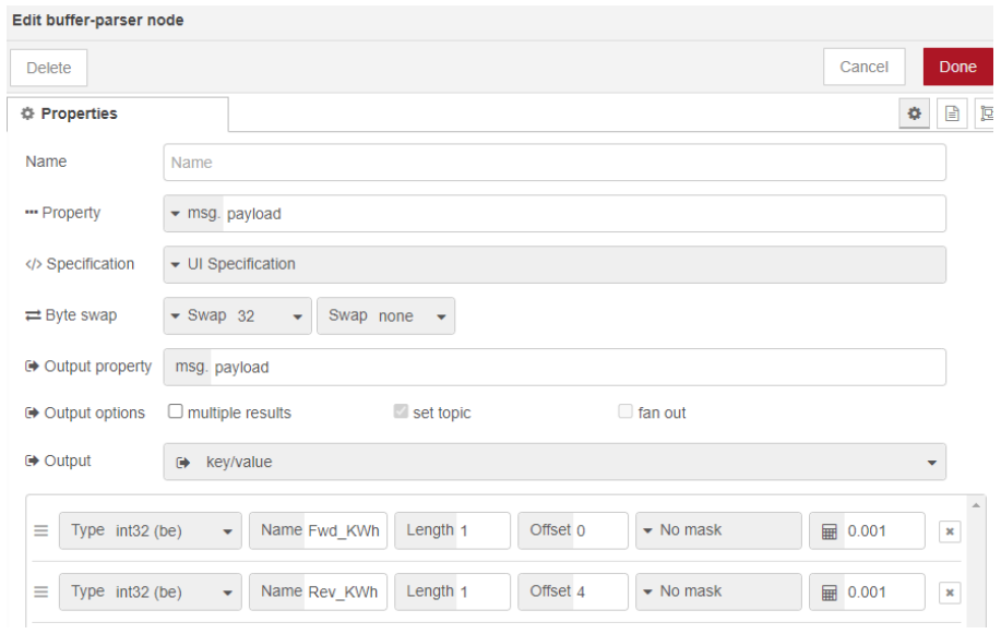
Install the ‘Bufferparser’. (Manage palette and search for ‘node-red-contrib-buffer-parser’)
The Bufferparser handles and changes the data from the files in /var/tmp and makes the data ready.
Afterwards the data is made ready in a function and finally sent by MQTT.
I also tried to make some ‘autodiscovery sensors’ for HomeAssistant.
Screendump of the Flow:
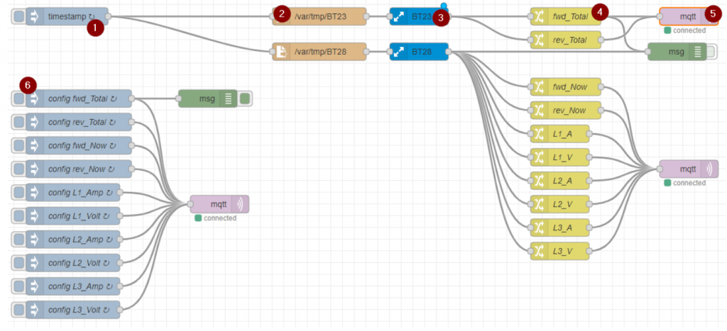
1. Timestamp runs every 10 secs.
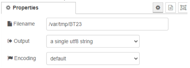
2. Function /var/tmp/BT23:
3. BufferParser BT23:
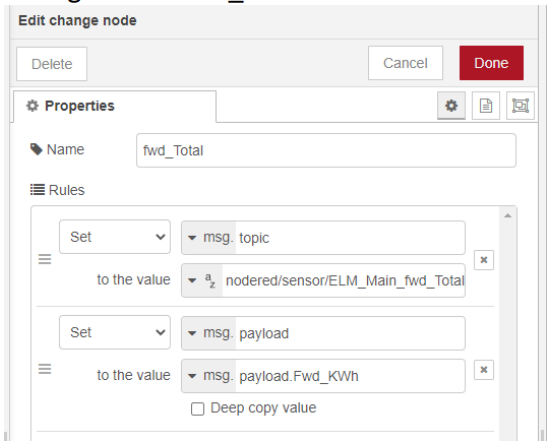
4. Change node ‘fwd_total’:
5. MQTT: Setup according to your MQTT broker settings.
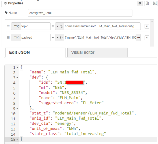
6. Discovery settings for HomeAssistant
Screenshot from HomeAssistant:
Hope this can inspire other to get data from ECHELON/NES meters via IR eye.
🙂 Ulrik, email: u_dabbler[AT]dumac.dk

This is a bonus entry on our blog in the Echelon/NES Smart Meters series. We have limited time and are devoting the sparse time we have on the hard- and software needed for the ESP32-MEP module. We are aware that other systems should be able to integrate to the solution, but we currently have no experience with stuff like “Home Assistant” etc.
This project was never supposed to be a dabbler.dk private project anyway. As you know if you’ve been following this blog, the end goal is to get the specification released. As soon as that happen we’ll release our hard- and software as well, and others can choose to join us in improving it, start their own project from the specs or even branch our project and move on from there.
We would love to see this grow in all sorts of directions…
Luckily others have more knowledge in integrating with “Home Assistant” and one of the more persistent persuaders must have been Jan Nielsen. He got a private access to a webservice on Gert’s ESP32-MEP module to see if he was able to integrate to it…
…and best of all: when asked he immediately wrote this blog entry about it – sharing his findings. The rest of this blog post is written by Jan Nielsen, so send all praises and credits to him:
Jan Nielsen
Educated as Data Technician (Data Mekaniker) from EUC Syd in Sønderborg in 1997.
I have worked some years as a full-time developer; then switched over to system administration.
But still with an interest in automation when there is a need, and occasionally some hobby projects.
https://www.linkedin.com/in/jan-nielsen-21a5832/
Hi there, my name is Jan. Like I assume many of the people reading this, I have been following this blog for some time. I found it back in August 2021, after first seeing Gerts post at ing.dk.
At the time I had recently discovered the Home Assistant project. My interest was to get a chance to play around with Zigbee – more than Philips Hue allowed for.
Shortly after the August update was released. The big news there was an energy dashboard, and a few more things related to it like long-term statistics etc. In this context energy meant electricity consumption and production (solar).
Without digital access to the overall household consumption this was not really useful.
You can get Zigbee, Wifi, Bluetooth og probably Z-wave plugs that can measure power consumption, but it is only a portion of the consumption.
Some solutions for reading total electricity consumption:
At the end of January when I saw Gert mentioning some web service, my interest was raised further.
In the autumn I made a HA integration for Min Volkswagen. It simply pulled in data from a connectedcars.io API. I first learned about this API from Esben on tech at Youtube. However, his approach was to use Node-RED. This I found a bit cumbersome, especially with the location tracker that had to be configured in multiple places. So, I took the challenge and tried to write an integration for HA, which would be easy to use and configure.
The API was really easy to use as Esben had shown how to do it. The HA part was more challenging and had quite some learning curve, but by studying other examples, documentation and at times HA source code I eventually got it working, including a UI dialog for the initial configuration.
Back to the MEP webservice… if the dabbler.dk guys had made a webservice I would rather easily be able to pull this data in, similarly to how I had already done with Min Volkswagen. So, I reached out to Gert offering to be a tester 😉, but also to implement a HA integration that could consume the webservice. Due to the NDA Gert was, understandably, not that keen on the idea, but he did offer remote access to a webservice. As for the development process this would be perfectly ok, and overall bring us faster to my goal of getting this data into HA. So, I accepted Gerts offer.
So, I cloned my previous HA integration and started to adjust the API reader code. As the webservice is very simple this was mostly a matter of removing authentication, and code to handle multiple cars/devices from the same web service instance.
Simplified, the basic steps to read it looks somewhat like this:
try:
async with aiohttp.ClientSession() as session:
async with session.get(req_url, headers = headers) as response:
temp = await response.json()
if temp is not None:
_LOGGER.debug(f"Got meter data: {json.dumps(temp)}")
self._data = temp

except aiohttp.ClientError as client_error:
...
And next to adjust each value, named a sensor in HA, that I wanted to make available in HA:
...
sensors = []
sensors.append(MeterEntity(config_entry.entry_id, config["name"], "energy consumption", "", False, True, _meterclient))
sensors.append(MeterEntity(config_entry.entry_id, config["name"], "energy returned", "", True, False, _meterclient))
sensors.append(MeterEntity(config_entry.entry_id, config["name"], "voltage", "L1", False, False, _meterclient))
sensors.append(MeterEntity(config_entry.entry_id, config["name"], "voltage", "L2", False, False, _meterclient))
sensors.append(MeterEntity(config_entry.entry_id, config["name"], "voltage", "L3", False, False, _meterclient))
...
async_add_entities(sensors, update_before_add=True)

class MeterEntity(Entity):
"""Representation of a Sensor."""

def __init__(self, config_entry_id, meterName, itemName, phase, returned, entity_registry_enabled_default, meterclient):
"""Initialize the sensor."""
...
if self._itemName == "energy consumption":
self._unit = ENERGY_KILO_WATT_HOUR
self._icon = "mdi:home-import-outline"
self._device_class = DEVICE_CLASS_ENERGY
self._dict["state_class"] = "total_increasing"
elif ...

async def async_update(self):
"""Fetch new state data for the sensor.
This is the only method that should fetch new data for Home Assistant.
"""
try:

# Measurement
if self._itemName == "energy consumption":
energy = await self._meterclient._get_value(["Fwd_Act_Wh"])
if (energy is not None):
self._state = int(energy) / 1000
Within a day or so data started to roll in.
At first the webservice had the accumulated consumption, returned to the grid as well as voltage and current for each phase. As I find power more relevant, I had to calculate this from voltage and current. Since then the webservice has been extended with power readings and more.
When it all seemed to run smoothly, one day it turned out to have registered a humongous consumption.
Unfortunately, I did not make a screenshot of it before correcting the data, but here is what it normally should look like:
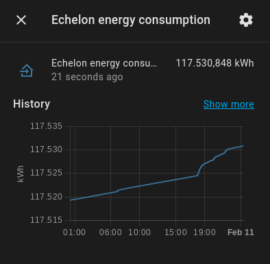
As it is the kWh counter it should be forever increasing. Little consumption will be slowly increasing, higher consumption will increase steeper.
When the problem appeared, it rose all of a sudden thousands of kWhs, and shortly after fell back to normal.
Due to the way I had defined the sensor in HA, this was a bigger issue than just that short glitch.
For it to be usable with the Energy dashboard it needs to have statistics collected each hour, and this requires a ‘state_class’ defined. For this kind of data it can be ‘total’ or ‘total_increasing’. To support meter reset the ‘total’ type requires a date specified where the meter was reset. Instead the ‘total_increasing’ type, which I had chosen, will see a decrease as a reset.
As the Energy dashboard works with the deltas, not only did the increase add thousands to the depicted consumption, when returning to normal it also added 117.000 kWhs because it assumed it was reset to zero and then consumed the reported value…
Gert had also noticed this at times, and had also mentioned it to me earlier. But in my rush to get something to show up I had also totally forgotten about it.
Rather than having to specify a reset date or risking negative consumption, I decided to continue with ‘total_increasing’. However, I did implement a limitation that would sanitize the kWh reading. If it increased more than 1000 Wh or decreased from the latest reading, it would discard the new value for up to an hour until finally accepting the new value if not returned to a more realistic value. It is only done in memory though, so not totally fail proof if HA is restarted during an issue, but it minimizes the risk.
A few days later Gert reported the issue had been found and firmware updated.
At the same time there was more info added to the webservice.
In a previous blog, it was shown that it could return info about itself like manufacturer, model and version. Although secondary, I find it nice and convincingly to have that reported as well.
Not only did the added info have metadata about the meter, it also turned out that similar data about the MEP module had been added.
In HA a device only has a predefined set of properties. So, how to depict both sets of device info?
Although not originally planned, it turned out simple enough, just make it appear as two devices. The meter itself and the MEP module:
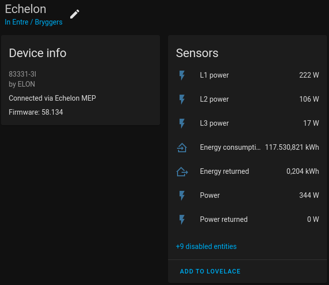
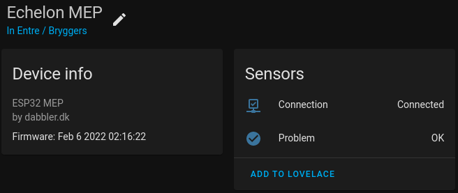
To do this, it requires at least one sensor on the MEP module. This is because it is the sensor that returns info about the device it is part of.
In this case I invented two binary_sensors that tell something about the status. One if the last http request succeeded, and two if the data returned doesn’t look as expected.
The “Connected via” relationship was new to me, and also something I wanted to try out… 😁 But it just worked, so no challenge in that.
As Gert and Graves had taken care of the difficult part, the most challenging part of this integration turned out to be the Configuration button, or as it is known internally the OptionsFlow.
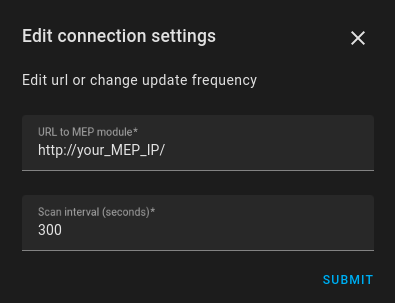
This I had not made with Min Volkswagen. The UI itself was not much different than the initial configuration, but I wanted it to be able to update the url to the MEP module and to change the scan interval (how frequently it polls the webservice).
The challenge with the url was that configuration and options are stored under different keys. And I didn’t like the idea of writing to both keys, and then making sure to read the right one if both were present.
Although I thought it would be a normal use case, I had to find a way to do it in a community thread where other developers had the same need.
Even worse when I wanted to make the scan interval configurable.
Gert had expressed concerns about the ESP32 being overloaded with requests, so I decided that polling it every 5 minutes would be sufficient for many use cases. In particular if the primary interest is the total kWh reading.
However, if you are interested in checking the power usage right now and want to see the difference when some device is on or off you need much more frequent updates.
Although you can buy plugs with the ability to report the consumption for a specific appliance, let’s also enable use cases that require readings from the meter almost as frequently as you might like for whatever purpose. When you have it in your own home and only polled by you, it is of much less risk of being overloaded than the module being exposed online right now.
HA has a really simple way for an integration to set a scan interval. It is a hardcoded value that I have not found a way to change dynamically. For integrations not using ConfigFlow and OptionsFlow it can be set in the configuration file, but making this apply requires a restart…
After studying other examples, I ended up disabling the built in triggering mechanism. Instead setting up a timer, that would fire an event to the sensors when it is time to update.
A change in the OptionsFlow dialog will reload the integration anyway, so although the timer is set up at load time it will update the timer interval when changed.
Besides the expected benefits, being able to reload the integration also turned out to have other advantages. Now it can unload the integration without restarting HA core, or enable and disable sensors without restarting. Just a much more convincing experience.
The integration is made publicly available for anyone to use. But to be usable in any way you will also need the hardware and not least the firmware, which currently awaits release from the NDA. So, continue to keep an eye on the blog for updates.
The integration can be found here: https://github.com/jnxxx/homeassistant-dabblerdk_powermeterreader
You will also see more screenshots in the README file.
Be aware that it does not contain any information about the MEP protocol. It just consumes the webservice provided by the ESP32 firmware, that is where the secret source is.
For ease of use and installation, I will try to get it into the HACS community listing of custom integrations.
The challenge will be if we can get a logo accepted, which is required. I already experienced once it is not so simple if you do not own the trademark rights. So, now we try to put it under the dabbler.dk name and logo.
Until included in HACS, you can add the url above as a repository to HACS yourself (as described in the installation instructions) and it will work just like it was. Only thing missing is the logo in the integrations overview.
Sorry it’s been some time since the last update – but please read the comment sections on the older entries – this project is still kicking, and we try to find time to at least answer the comments.
Let us admit – we were worried… It seems NES went into some kind of radio silence mode during end of 2021 and start of 2022 – but finally in mid January we manage to get a hold on them.
They apologized that the MEP-protocol specifications was delayed – the team simply had to work on other more urgent projects… We fully understand that stuff can get delayed when you are “hit by reality”. After all – this release is for the community, not something a company can pay their bills with :-). And Graves and Gert also have to attend their day job to get bills paid. This is – after all – only a spare time project.
Anyway – NES assured us that it would now get prioritized a bit higher again and hopefully soon be finished.
BUT EVEN BETTER – earlier this week, Gert received a draft PDF with the “release version” of the “MEP Client Developer’s Guide”. This shows us that NES are still actively working on this. Due to the NDA we cannot share much, but you will find an image of the cover page as the featured image of this entry.
It is clear that this is still supposed to be released through OSGP Alliance. Just like promised previously by NES.
A quick glance through through the PDF shows that the document has been revised, even improved a lot. And – more important – it seems that most of the protocol is still in there… So this is REALLY good news. We’ve promised to proof read it a bit and give feedback. But we are really looking forward to be able to link to the release when it is ready.
Sorry for this short – but at least positive – update.
We’ll get back to you with progress on software and hardware soon. And hopefully also soon with some news about the release of the documentation.

As mentioned in our previous post, we f***ed up the connector to the meter…
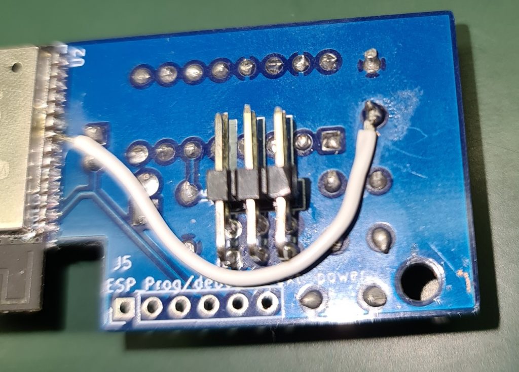
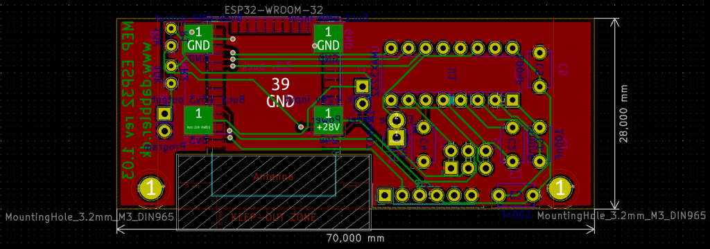
Moving on and with a few other hardware versions that never got produced, we ended up having a version 1.03 prototype where the connector is fixed and that kind of works most of the time in some meters:
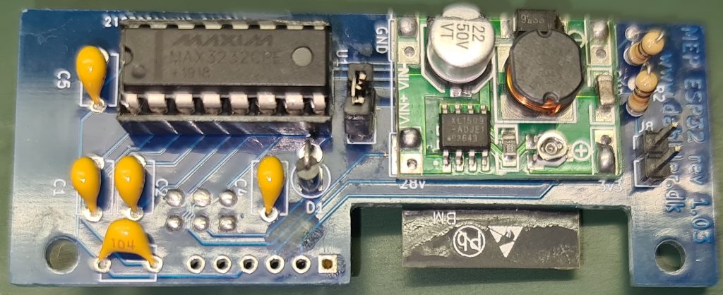
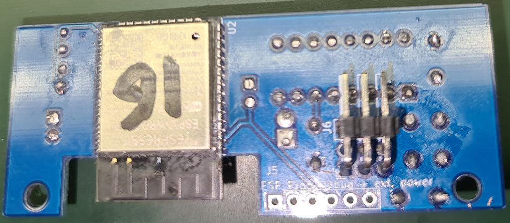
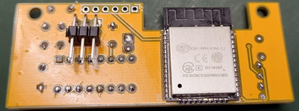
Note: jumper for disconnecting power (while adjusting the buck converter) was introduced. And also a “Set ESP32 in programming mode” jumper replaced something we tried to do that never worked :-). The unpopulated 6 pin connector is matching a standard FTDI USB to TTL Serial 3.3v Adapter and can be used to flash or debug the ESP32.
Now we have something kind of working, but are struggling with stability. Which was actually quite a surprise for us. We acknowledge we are mostly software guys, but this hardware is soooo simple – what can really go wrong?
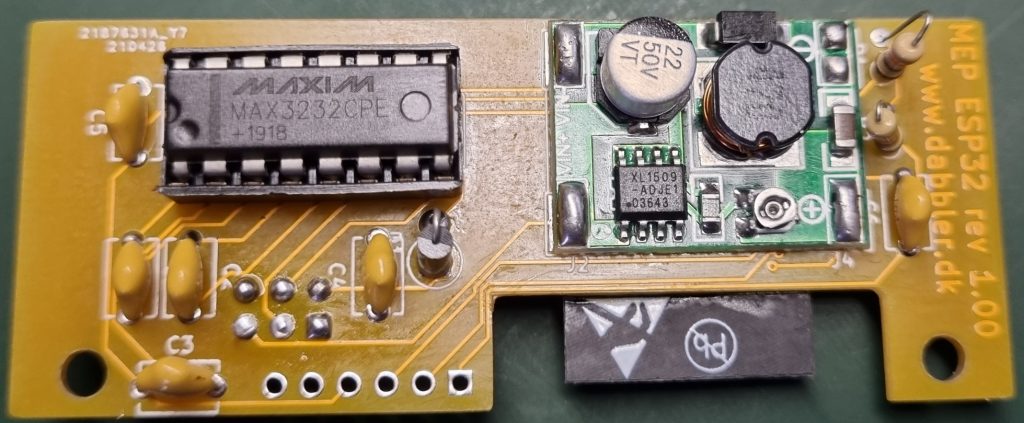
It seems Maxim Max3232 ICs are quite commonly faked in China – and since we buy most of our components in China, we have been struggling with 50 ICs that simply did not work (we got a full refund) and multiple batches that are just misbehaving a bit.
Apparently most of these Maxim Max3232 fakes seems to kind of work, but sometimes when they are powered on and the RS232 pins are connected, the build in boost converter will go haywire. The communication will not work and they will get VERY hot.
If you disconnect, leave the IC to cool off a bit and then reconnect. It will sometimes fail and sometimes work. In some meters it will fail more than in others… A quite intermittent and confusing problem…
You can google this problem – it is quite easy to find others with problems like ours and even with solutions that fixed it for them. We are working on trying out which solution will fix it for us – but this takes time when it sometimes works… And when you think you nailed it, it comes back and bite you in the b**.
Note: If you have any info. on how to fix this issue or issues like this, please let us know by writing a comment. We are for sure NOT electrical engineers and will probably end up creating some kind of software solution for this if everything else fails ;-).
The right (also morally right) solution would off cause be to buy genuine Maxim Max3232 and don’t support the Chinese companies producing fake chips. But the genuine Max3232s are actually quite expensive for “poor” tinkeres like us :-). Let’s see if we can design around this flaw and make something that simply works – even if you use semi working fake chips. After all – it is just another challenge and we started this project to push the limits in the first place…
So for sure, if you want to create hardware from the current design, it is on your own risk. Note: the final solution will also be at your own risk, but this prototype is just even more unreliable than what we usually create :-).
Disclaimer: We cannot be held liable for anything written on this site – even if you set your meter, yourself or your building on fire!
Off cause you also won’t have much use for it before the MEP documentation or our software is released.
Anyway – the current unpopulated prototype PCB looks like this:
As we chose to use thru hole components we are kind of “out of space” (which is defined by the size of the “drawer” in the meter). So we are considering pushing our soldering skills and going to SMD components to get more space… Maybe in a future prototype?
The current schematic (without any fixes for fake Max3232s) looks like this:
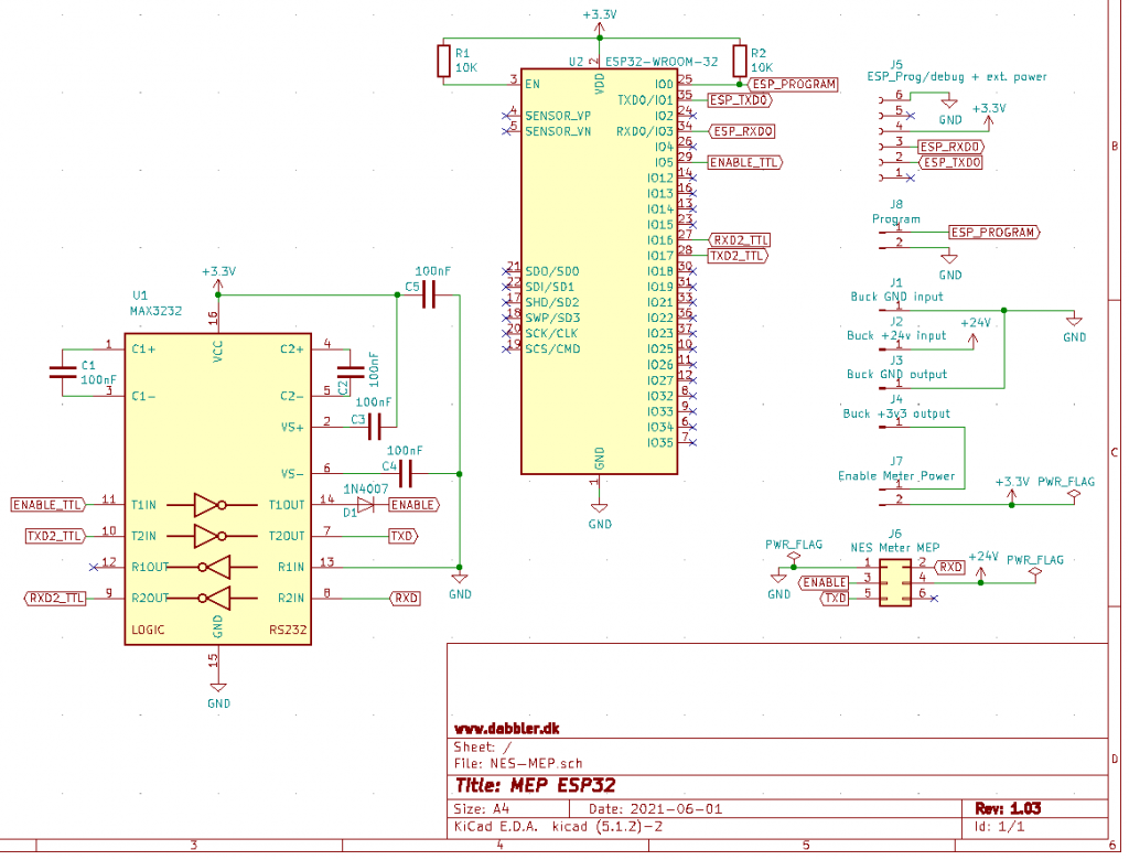
Warning: The schematic still have the wrong pin numbers for the MEP connector, so don’t trust those! The wiring is correct, but the pin numbers shown are not!
The Max3232 is more or less setup like the reference diagram in it’s datasheet. So not much to explain there (the capacitors are used for the build in boost converter converting the 3.3VDC to the +/- DC voltages needed for RS232 signals).
A Max3232 got two sets of receive/transmit logic. We currently use the first set for the actual communication with the meter, and (mis-)use the second set to set the Enable pin high towards the meter (it might not be exactly +5VDC or +12VDC, but it works). To prevent the Max3232 from setting the Enable pin negative, we have a diode in there (not that we know for sure it is needed 🙂 )… We currently have no use of the receiver part of the second set of the Max3232 receive/transmit logic, so it is just grounded on the RS232 side to prevent it from oscalating.
The resistors connected to the ESP is just to make the initial flashing through the J5 connector work.
Nothing real fancy going on in the schematic as far as we are aware :-), but as mentioned a few stability issues with some meters… So we are trying out different solutions for that.
Btw: if anyone need a copy of the current KiCad project while we wait for something better, feel free to e-mail us. We’ll be happy to share it, but prefer not to put it up for download until we have sorted out the hardware bugs…
Unfortunately the software is covered by the NDA, so we cannot share that yet… So you really have no use for the hardware at this point in time…
As soon as we are released from the NDA with NES, our plans are still to make both hardware and software fully available to you … on this dabbler.dk-blog.
Stay tuned!
Let us finish with a sneak preview of a few decoded meter answers from our software:
Note: Our added comments are formatted with italic. L1 L2 and L3 is the name of the 3 phases measured by the meter. *’s are replacing the stuff we are not allowed to share yet due to the NDA:
0x** Invalid sequence number (this is normal for 1st request)
The meter returns the sequence number to use for the following requests with this error
0x** Successful response
This is some initial reading of the meters setup. It is required to decode some of the other messages correctly.
Flags 0: 0b00000011
Flags 1: 0b00001100
No. of Self-reads: 12
No. of Summations: 11
No. of Demands: 0
No. of Coincident Values: 0
No. of Occurrences: 0
No. of Tiers: 0
No. of Present Demands: 0
No. of Present Values: 55
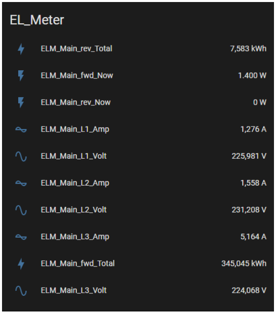
0x** Successful response
Manufacturer: ELON
Model: 83331-3I
Version: 58.134
0x** Successful response
This response is about aggregated consumptions.
The meter’s display was showing: 115921 kWh when this was received.
This household is NOT producing electricity, so the 201Wh might be from when the meter was initially tested?
This response contains far more values than the ones we chose to decode.
Fwd Active Wh L1L2L3: 115921469
Rev Active Wh L1L2L3: 201
0x** Successful response
This response tell us about the current consumptions etc.
This response contains far more values than the ones we chose to decode.
Fwd Active W L1L2L3: 701
Rev Active W L1L2L3: 0
Import Reactive VAr L1L2L3: 139
Export Reactive VAr L1L2L3: 0
RMS Current (mA) L1: 1536
RMS Current (mA) L2: 1874
RMS Current (mA) L3: 139
RMS Voltage (mV) L1: 232591
RMS Voltage (mV) L2: 233879
RMS Voltage (mV) L3: 234387
Frequency (mHz): 50000
VA L1L2L3: 822
Power Factor L1 (1/1000): 875
Power Factor L2 (1/1000): 836
Power Factor L3 (1/1000): 837
Fwd Active W L1: 311
Fwd Active W L2: 366
Fwd Active W L3: 25
Rev Active W L1: 0
Rev Active W L2: 0
Rev Active W L3: 0
RMS Voltage (mV) L1 – Continuous: 232507
RMS Voltage (mV) L2 – Continuous: 233922
RMS Voltage (mV) L3 – Continuous: 234246
RMS Voltage (mV) L1 – Average: 232185
RMS Voltage (mV) L2 – Average: 232990
RMS Voltage (mV) L3 – Average: 234229
Average Fwd Active W L1L2L3: 701
Average Rev Active W L1L2L3: 0
Average Fwd Active W L1: 311
Average Fwd Active W L2: 366
Average Fwd Active W L3: 25
Average Rev Active W L1: 0
Average Rev Active W L2: 0
Average Rev Active W L3: 0
0x** Successful response
Utility Serial Number: 4080******(digits removed manually on this blog for security reasons)
Image CRC: 55331
Unfortunately we are still awaiting the release of the MEP protocol from NES (Networked Energy Services) as mentioned in previous blog entries. This will release us from the Non-Disclosure Agreement (NDA) keeping all this a secret to you.
…but while we wait, we could introduce you to our hardware prototype.
In our first few attempts we got the connector totally wrong.
Apparently the footprint we used while doing our PCB design numbered the pins 2 columns in 3 rows, while NES numbered them with 3 columns in 2 rows:
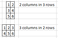
Naturally we messed that up! Luckily we actually did some sanity testing before just inserting this prototype into the meter, and we did discover the error and simply connected with some wires to quickly fix it.
We wrote about the pin connections previously, but just to recap:
Pin 1: Ground
Pin 2: Enable. Set to +5VDC or +12VDC to tell the meter the MEP interface is active
Pin 3: TXD (meter’s serial receive pin)
Pin 4: RXD (meter’s serial transmit pin)
Pin 5: Power. +24 or +26VDC (max 1W) from meter
Pin 6: Not used / no connection
Note: It depends on the hardware model of the meter if pin 5 supplies 24 or 26VDC.
Due to the wires, we could move on with the software… While awaiting a new prototype PCB from JLCPCB… But let us explain a bit about the hardware prototype:
The ideas behind this hardware are quite simple:
Not much to it – or is it really this simple?
Stay tuned for an update on the next hardware version of ESP32 MEP…. Coming to www.dabbler.dk real soon now…

As mentioned in our previous post, we we stuck. We had a 3rd party module which were clearly communicating with the meter through RS232. We knew the hardware interface, but we had no idea about the protocol…
In pure desperation we opened a support ticket with the current owner of the technology – NES (Networked Energy Services). We did not expect any feed back – or at least no help. Surely they know the port and the protocol, but we did not expect us beeing able to reach out to them directly… We more or less expected that they would simply redirect to our power company or power grid/meter owner…
In fact they responded positively to our request, and soon setup a teams call between us and a Senior Vice President. During the meeting they simply wanted to know if we were tinkering or doing a commercial product, but as soon as it was established that this was in no way commercial, they were prepared to offer their full help.
Apparently NES is working on opening the reading part of the protocol up, so our timing was perfect. Unfortunately they were settled about how to do this and how to approach it. So they needed us to sign a Non-Disclosure Agreement (NDA) to get access to the full documentation. As the NDA only covered un-released documentation, they promised to work on figuring out how and what to release asap so the NDA could be lifted. While writing this, we have received the finished documentation for the IR-interface (which we cannot use for anything in Denmark as N1 claims it is fully encrypted, and N1 will NOT release the encryption keys due to security considerations). Also we have received a preliminary draft of the MEP documentation, so we trust this WILL in fact be released soon (according to NES the deadline is Q4 2021).
We can reveal a few things about the protocol – which is more complex than we expected. The meter has around 80 tables you can read and/or write to and around 30 procedures you can call (individually and/or as part of an atomic transaction). We are told not all tables and procedures will end up in the public documentation, but the full protocol supports stuff like: writing to parts of the meters display, report data from other meters via MEP and let the meter report it to the grid. Let the grid send firmware/files to you module. Read out all aspects of the power delivery – like consumption, quality, outages etc. The meter can even send and receive alarms if something unexpected happens or ask you for measures if you configure it to include data form other meters (i.e. water, heat etc.) in it’s reports to your net company…
If this was just a matter of only allowing reading from the meter it would be simple, but unfortunately some of the reading required setting up stuff and writing procedure calls to tables… And the reading the results from other tables. So it is far from simple and NES need to make sure that the parts released is just enough without beeing too much…
Note: although MEP is unencrypted a password is needed. There are 3 levels of security in the MEP protocol. The password is used as part of a digest (checksum) calculated on the data packages and reply. It is used to make sure the requester has the proper access, but also that the sent and received packages are not corrupted during transmission.
These keys should be provided by your power network operator (i.e. N1). Those are the ones owning your meter and the cable to you house.
Regarding N1 they are only willing to give us the MBK, but it is fine as it can be used to read most values from the meter. We were told that the MBK is shared between meters, while the MAK is a individual key per meter.
If your power network operator is N1, the procedure is to ask the power company (the ones you actually buy your power from) to ask N1 provide the read-only key for reading out power consumption electronically (they can do this by using a N1 webform created for this purpose. You also need to provide your name/address, and probably also installation no. and meter no. And off cause your e-mail address.
At the time of writing this is the current state of the project:
Rest assured that we will share the software and related knowledge/hints as soon as the NDA is lifted… Follow our blog to get notified when this happens…
In the meantime we could probably soon share our hardware… Stay tuned 🙂

www.sommerhack.dk 2020 renewed our interest in communicating with our Echelon meter. During a session by Thomas Ljungberg Kristensen, WelcomeSecurity (https://www.welcomesecurity.net/) the different possibilities and the legislation was briefly covered and he inspired us to push harder to get some kind of access.
If you are following these posts, can read Danish and have a Smart Meter you would like to connect to – this page (created by Georg Sluyterman) might be of interest to you: BefriDinElmåler.dk.
As mentioned in the previous post we already started the process of getting further information from N1. The useable information was sparse and hidden in a lot of mis-information, but in hindsight we know that this was probably not on purpose, but simply because the N1 organisation and staff did not have the full picture of the solutions and/or simply did not know better. This simply seemed to be new to everyone involved…
N1 confirmed that the IR solution was encrypted and there were no way they could supply us the encryption key. Supposedly there were a hidden port behind a cover at the bottom of the meter, and we should purchase a “Izar / M-bus PCB” for it. We were a bit skeptical, but did find a hidden 6 pin interface in a plastic drawer on our meters… So it seems there were some truth to this…
N1 told us that a company called Develco had been involved in the developments, but had sold off the solution to an unknown 3rd party… Gert discussed a bit with N1 if they could claim that we could simply order this PCB, when it was nowhere to be found and they could not tell us where we could buy it… Is something REALLY for sale when you cannot buy it? 🙂
After researching this further Izar and M-Bus interfaces seemed to be a dead end… But researching “Develco”, hidden interfaces and solutions further we found this! (local copy of the PDF can be opened from here if the external link ever disappears)…
But wait a minute – this document does not mention “Izar” nor “M-Bus”!!! Insted new terms like “Multi-purpose Expansion Port (MEP)” and “ZigBee” is introduced. What the heck is a MEP port?
According to the document the Danish company Develco was actually involved in a project with EnergiMidt (parts of EnergiMidt are now N1) and NES (Networked Energy Services). And apparently as part of selling all these Echelon Type 83331-3IAAD (and similar model) meters in Denmark, a new plastic cover was developed providing access to the MEP screw terminals from a small “drawer” in the meter! It seems this solution is available for most (if not all) Echelon Type 83331-3IAAD (and similar model) meters in Denmark.
Unfortunately it was very hard to get in touch with Develco. We tried multiple times writing them, calling them etc. Finally Graves managed to convince a sales guy that we represented a company interested in purchasing SEVERAL PCBs to follow multiple plants power consumption more closely…. Only to discovere that the PCB never was produced as anything but a prototype / proof of concept… They would be happy to start production up for us , if we would only place an order of of 10,000 pieces or so…. Yet another dead-end…
The MEP “drawer” is well hidden. We did not know it was there before we found this document. As far as we know other tinkers investigating this also did not find it (or at least the few we spoken with afterwards didn’t know about it). This is simply a well hidden “secret” in plain sight. It looks like part of the cover, but it is actually a separate piece of the plastic you can pull out and it is prepared to receive a small PCB that connects to a 6 pin standard 2.54mm pin header. When you know it is there, it is obvious – we just didn’t notice it previously…
We tried to investigate the 6 pin interface, but it is hard when you have nothing communicating on it – and no idea what exactly to look for. If we could just open the sealed meter to reverse engineer – but that is illegal.
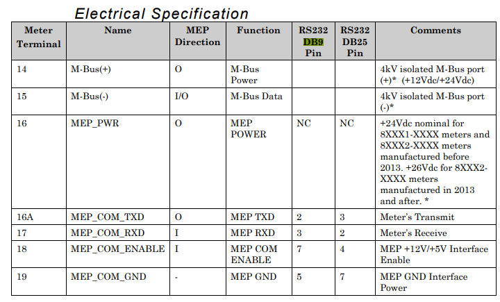
At least we found this in a manual forwarded to us (although it is marked CONFIDENTIAL), but it does not tell us how the pins are routed to the 6 pin header:
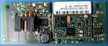
Inspired by Thomas – we pushed harder – and (we cannot reveal from where) “suddenly” we had a prototype of the so-called “Izar/M-Bus PCB”. This was really a breakthrough. We immediately tested it in a couple of Echelon meters, which immediately recognized it with a small “M” in the display. And according to the available documentation – that is the “icon” for a MEP device (Multi-purpose Expansion Port) and not a M-Bus device… So Izar/M-Bus appears to have been mis-information… This is in fact a MEP/ZigBee PCB…
Anyway – with a working PCB to reverse engineer and the above table, we soon found this pin-out of the “secret” 6 pin header (pins from top left to bottom right as seen when you look at them in the “secret” drawer in the meter:
And also the above table confirms that MEP is a quite simple serial (RS232) based protocol.
Based on this we were soon able to capture communication with a small PCB between the meter and a couple of USB RS232/DB9 interfaces (like these)… We soon realized the serial communication parameters 9600,n,8,1 and to our surprise the protocol seemed binary and far more complex than expected…
During our early research we stumbled across this GitLab project. Looking at it, it seems MEP is a kind of clear text protocol with quite simple commands, but we soon realized this was another “rabbit hole” or we simply do not understand the code in the project. Anyway – it seems we cannot get any usable knowledge from that project.
We tried to research the protocol, but the only stuff we could find was that Echelon at some point sold training in this, and then references to this document “Echelon Corporation (2010c) MEP Device Developer’s Guide, Version 078-0372-01G, San Jose.”.
We also tried to reverse engineer it based on the recorded packages sent and received between the MEP/ZigBee module and the meter – but this was clearly outside our skillset. We had NO idea what was sent and received…
We were giving up after “hitting this wall” of the secret MEP protocol…
…and in our desperation we reached out to what we thought was the most unlikely party to help us (no, not N1) – stay tuned for our next post :-)…