(Guest writer) Echelon/NES Smart Meter – FHEM integration in Austria

FHEM Home Control

Back in June 2022 Engelbert Horvat reached out to us to discuss a MEP solution for his Echelon/NES Smart Meter. Engelbert lives in Austria, so unfortunately our module is not a good solution for him. Although the MEP electrical connections and protocol is standardized in these meters, the MEP “drawer” our modules are designed for is a Danish thing – and has even been abandoned in the NES Smart Meter Generation 4 on the Danish market. Note: It would be possible to use our module, but it needs to be connected by wires and one should probably also create an enclosure for it.

Luckily Engelbert is also a fellow tinkerer, so although we inspired him, he developed his own hard- and software solution. To get people to do this has always been our mail goal and we asked him to tell his story as inspiration for others:


Hi, my name is Engelbert and live in Austria in the city of Amstetten which has its own power supply company (the “Stadwerke Amstetten”). They have around 12000 Echelon/NES Smart Meters installed. I wanted to interface with my smart meter and send informations via MQTT to a home automation system (FHEM in my case).


First contact and tests in June 2022:
I was asking “Stadwerke Amstetten” how to interface with their smart meters and eventually was finding the right person who had very good knowledge and enough motivation. To my surprise he gave me a spare NES smart meter just for testing, “I can fool around with this a bit for the next few month or so” he told. Also I got a xml file with the basic Encyption key (MBK) for this smart meter. So no problem with obtaining a MBK at all….my thanks are going out to Stadwerke Amstetten. But I was told that it is not so easy to get out data, and also that I was first one who was asking for this in Amstetten.

Finding the Echelon/NES smart meter informations on the dabbler.dk site was just great and I did hope to be able to go on with this.

Gert was providing me with the current (at the time prelim) ESP32 MEP interface software, and some installation hints as well. (They where mostly in Danish language, but Google does a great job in translating…).

So I wanted to get some readings from the smart meter quickly….

Hardware wise I had a ESP32 Module (ESP32 Dev. Kit) which is supplied and programmed via a micro USB port. Also I found a old MAX232 (exactly a MAX232ECPE for 5 Volt !) and the capacitors in my electronics storage. Because MAX232E is a 5V but ESP32 is a 3.3V device level shifting for the RX data out of the MAX232 must be done. I did just a simple voltage dividor with 2 resistors (1k / 1.8k). For the TX signal to MAX232 I was hoping that ESP32 delivers enough voltage for the 5V logic of the MAX232. So I came up with a simple schematic – basically a stripped down version of the NES-MEP from dabbler.dk, including now a ESP32 Module. Please visit https://github.com/ehorvat1/NES-MEP-Reader/tree/main/Hardware and look for the file NES-MEP-5Volt.pdf.

I have checked also some voltages and power consumptions. MAX232 provides 2 voltage charge pumps and their output can be measured on pins 2 (VS+) and 6 (VS-) . Note: using 100nF caps for a MAX232 is a bit out of spec. Caps should be 1µ for MAX232E but 0,1µ for MAX232A or MAX3232, but it was working well and I could easily exchange the MAX232 with a low volt MAX3232 later. At a power supply of 5V the MAX232E gave 8.2V on VS+ and -7.3V on VS- during operation.

I have also tested on 3.3V level with a MAX3232 in combination with a LM2596S based step down converter. At a power supply of 3.5V the MAX3232 gave 5.8V on VS+ and -5.5V on VS- . All supplied by the NES Smart meter 26V output which used then app. 18mA on average, with some short peaks due to Wifi communication up to 30-40mA (and this may lead to problems – see notes at the end.)

Software wise was also no big deal with a little help from Gert.

Please note that the MEP basic key (MBK) comes in different forms:
a) ASCII which should be 20 characters long similar to this: a7941d85bce8a8fa2ab7 .
b) HEX representation of the ASCII format which would be similar to: 6137393431643835626365386138666132616237 so this is 40 char long where ASCII is shown in hex (ASCII a = 61(hex))
c) Decimal representation of the ASCII format which is like hex, but each ASCII is shown in a decimal.

Final (…kind of) PCB design Aug 2022:
I have designed now a PCB which holds the MAX3232, a ESP32 Module and a DC/DC converter to 3.3V.

Another issue is how to physically connect to the MEP port in a home environment. At my place the MEP port terminals are covered by the lower plastic cover which is sealed off by the power company in my case – it is not allowed to cut the seals !!. As a first try “Stadwerke Amstetten” would be ok to take the seals off so I can put the hardware inside the NES meter covers. But I did not like that, I want the NES-MEP-ESP32 to be easily accessible. So I have convinced them to to another solution.

Which is that the owner of the smart meters (the power company) will open the sealed off cover and install a little connector to the MEP port terminals which are then routed outside using a 6-wire flat ribbon cable. The flat ribbon cable fits through the gap of the plastic cover on the back of the meter and the hardware can be placed outside the meter. The smart meters have to be excanged on a regular basis (3 years ? For calibration checking) so this must also be taken into account.

Github Repo Nov. 2022:
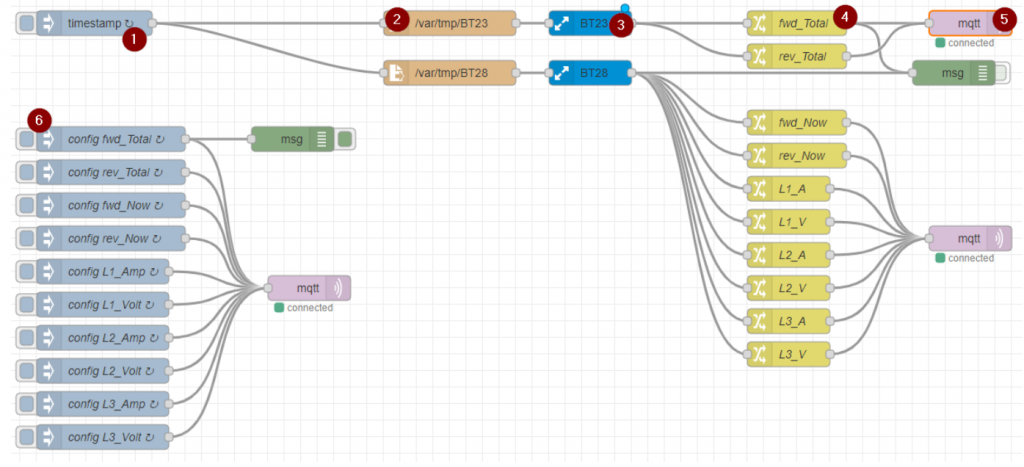
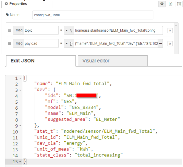
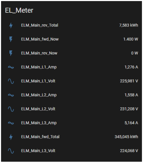
I wanted that ESP32 is sending NES meters data via MQTT to my home automation system. So I stumbled over a nice project on GitHub called AMS2MQTT Bridge (https://github.com/gskjold/AmsToMqttBridge) and modified this to read data via MEP port from the NES smart meter. You can find this on my GitHub at https://github.com/ehorvat1/NES-MEP-Reader. You will find there also detailed info about the used hardware.


Notes:
1) I have found that NES meter power supply is quite limited and on some meters just too less power is provided to drive ESP32….which is no big deal since I am using ESP32 Modules anyway which have an USB port for programming and power supply. So for some (I had only problems with NES Smart Meters Type 83332-3I)

2) My software uses the hex format of the MBK Key and not the ASCII representation used in Gerts NES-MEP software. The “hex” MBK is 40 char long as each ASCII is represented by a 2 digit hex number.

Kind Regards,
Engelbert Horvat

(Guest writer) Echelon/NES Smart Meters – NES/ECHELON electrical meter connect to MQTT (Home Assistant) via IR

MQTT and IR

This is another bonus entry on our blog in the Echelon/NES Smart Meters series. As we have mentioned before, it is sometimes hard to find time besides our regular jobs to dabble with this project. We have had a lot of interest in using the IR (Infrared) port on the Echelon/NES Smart Meters, and there have been (at least with N1) some confusion about if it was encrypted or not.

We know that someone at Sommerhack 2021 had been told by N1 that they should be able to use the IR port and that the key was the same as the MBK used for the MEP communication. We have not tried that ourselves as we have chosen to focus our limited time on the MEP integration. And to our knowledge – nobody else have tried the IR approach – that is – until now :-).

Our fellow tinkere Ulrik was faced with the challenge that his power supplying company Konstant, does not allow him to use the MEP-port on his Echelon meter. They are simply following another approach compared to N1, and suggests that their customers should use the IR-port.

Overall/political speaking this is actually really good news. Because if N1 can allow us to use the MEP port in a safe way, why should Konstant be against it for security reasons? Why should they not agree to allow it sometime in the future if they are pushed?
Also – if Konstant can allow their customers to use the IR port in a safe way, why should N1 be against it for security reasons? Why should they not agree to allow it sometime in the future (if not already?) if we push them?

Some have been dreaming of being able to interface with the Echelon/NES meters for years – but it was not possible due to a lot of “red tape”. Maybe we now have or will get TWO separate interfaces for interfacing with Echelon/NES Meters?

Enough dabbling with words from dabbler.dk – let’s hand over this scene to Ulrik and let us hear what he was actually able to do with the IR port:


First of all, I would like to say thank (and sorry) to Gert and Graves for letting me ‘spam’ them with my thoughts, questions and discoveries. And of cause for helping me out from time to time :-).

INFO:
My name is Ulrik and I work as an Automation technician. I started out as an electrician and was fascinated by all the technical stuff you could do. I have around 30 Years of technical background. I build my own house in year 2000 where I put in a PLC to control the house. All lightning, heating, ventilation and alarmsystem is run from that.
Well… Back on the track… I started out collecting the pulses from my main meter by using the S0 pulses. Worked great, until I got solarpanels installed and the meter now send out pulses whenever a watt was produced or consumed, so not that usefull :-(. Then I started looking at other ways and stumbled over a lot of options, among this was the IR port. So here’s a story of how I got this to work :-).
I have a NES 83334 meter. I also use Home Assistant.

I have very little knowledge of Python and NODE RED, so ‘Google was my friend’ 🙂
I also know that this setup could be much more ‘smart’. But for now, it just might get people started to get data from the meters 😉

My supply area is KONSTANT and they will send you the decryptkey if you contact them at info@konstant.dk

They also send me a draft version of Optical Port Programmer’s Guide with some info tables in the meter.

KONSTANT also told me that the meters they are using (ECHELON / NES) have the MEP port disabled, so I was unable to use that. So I went the optical IR eye way…

Communication parameter that I use:
9600, 8, 1, none

LINKS:
Install a RAM disk (to prevent destroying the SD card.)
https://www.hellojona.com/2017/06/create-a-ram-disk-tmpfs-in-raspberry-pi-3/

ANSI C1218 protocol description:
https://kupdf.net/download/ansi-c1218_598ceccadc0d606c4b300d1a_pdf

ANSI C1219 Protocol description:
https://kupdf.net/download/ansi-c12-19-2008_5af9fdd5e2b6f501147de395_pdf

Open Smart Grid Protocol (OSGP)
https://www.etsi.org/deliver/etsi_gs/osg/001_099/001/01.01.01_60/gs_osg001v010101p.pdf

Termineter (Framework for reading data from smartmeters)
https://github.com/rsmusllp/termineter

HARDWARE USED:

IR Probe:
I bought mine from Weidmann Elektronik
https://www.weidmann-elektronik.de/Produkt_IR-Kopf.html

1.00 x IR Schreib/Lesekopf USB (Optokopf), ART0027, EUR 44,99

I have not tried other probes, but I figured at the start of this project, I did not want to have trouble with my hardware. I know it’s kind of expensive but it works 🙂

Raspberry Pi 3 model B+ with 8 gb SD card:
(I used Raspberry Pi Imager and installed Raspberry Pi OS)
Activate VNC and SSH (Raspberry PI configuration – Interfaces)

SOFTWARE:

Install SAMBA

sudo apt install samba samba-common-bin

Edit the config file:

sudo nano /etc/samba/smb.conf

[pi]
path=home/pi
read only = no
writeable = yes
browseable = yes
guest ok = yes
create mask = 0755
directory mask = 0755

Press CTRL-o and CTRL-x to save and exit

Install a RAM disk (to prevent destroying the SD card.)
Link: https://www.hellojona.com/2017/06/create-a-ram-disk-tmpfs-in-raspberry-pi-3/

mkdir /var/tmp

Edit the fstab file.

sudo nano /etc/fstab

Add the following line to /etc/fstab to create a 400MB RAM Disk

tmpfs /var/tmp tmpfs nodev,nosuid,size=400M 0 0

Execute the following command to mount the newly created RAM Disk

mount -a

To verify the RAM Disk is created and mounted successfully, execute the following command

df -h

Temporary files can now be written/read to/from /var/tmp partition.

PYTHON 3.9 (I think that it is installed on the Raspberry by default).

Install NODE-RED
I think I installed it from the Rasberry Pi ‘recommended software’ via the GUI.

Autostart Nodered: (run from a terminal / SSH)

sudo systemctl enable nodered.service

Install Temineter (Python program to communicate C1218 and C1219 protocol)
Start a terminal and install it.

git clone https://github.com/securestate/termineter.git

Change permissions on directory

sudo chmod 777 termineter -R

I edited a some of files (I use Visual Studio Code through the SAMBA share) to get this to work.
You can use the files from the attached zip of use them as inspiration to copy/waste.

Changed files:
lib/c1228/connection.py
lib/termineter/core.py
lib/termineter/modules/get_data.py
lib/termineter/modules/read_part.py

TERMINETER program changes
lib\termineter\core.py:
*** Section around ‘Setup end configure options’

self.options.add_string('SERIAL_CONNECTION', 'serial connection string',default='/dev/ttyUSB0')
self.options.add_string('PASSWORD', 'serial c12.18 password', default='<your decryptkey here!>')
self.advanced_options.add_integer('C1218_PACKET_SIZE', 'c12.18 maximum packet size', default=64)

Run the program:

python ./termineter

Termineter
 <[ termineter v1.0.5
 <[ model: T-1000
 <[ loaded modules: 19

termineter >

Run the module to start getting data:

termineter > run get_data

Hopefully the program starte to get data (and save it in the /var/tmp folder)

[+] Successfully connected and the device is responding
[*] Read 8 bytes
0000 74 40 05 00 9f 1d 00 00                         t@......
[*] Read 40 bytes
0000 96 0a 00 00 00 00 00 00 00 00 00 00 39 02 00 00 ............9...
0010 f8 0c 00 00 dc 0c 00 00 90 19 00 00 27 70 03 00 ............'p..
0020 ef 6f 03 00 76 70 03 00                         .o..vp..

Instead of (or additional) to make the program changes, you can use a ‘resource file’ (look at
https://github.com/rsmusllp/termineter/wiki/GettingStarted at the bottom)

If you use a resource file, you can ‘autostart’ the program.

Errorhandling still needs to be taken care of 😉

NODE-RED Program:
The data from termineter is stored in /var/tmp BT23 and BT28 and is updated every 10 sec-ish.
I use NODE-RED to handle the data (and send them to HomeAssistant via MQTT)
Install the ‘Bufferparser’. (Manage palette and search for ‘node-red-contrib-buffer-parser’)
The Bufferparser handles and changes the data from the files in /var/tmp and makes the data ready.
Afterwards the data is made ready in a function and finally sent by MQTT.

I also tried to make some ‘autodiscovery sensors’ for HomeAssistant.

Screendump of the Flow:

HomeAssistant - Screendump of the Flow
HomeAssistant – Screendump of the Flow

1. Timestamp runs every 10 secs.

2. Function /var/tmp/BT23:

HomeAssistant - Function
HomeAssistant – Function

3. BufferParser BT23:

HomeAssistant - Buffer-parser
HomeAssistant – Buffer-parser

4. Change node ‘fwd_total’:

HomeAssistant - Fwd_total
HomeAssistant – Fwd_total

5. MQTT: Setup according to your MQTT broker settings.

6. Discovery settings for HomeAssistant

HomeAssistant - Discovery settings
HomeAssistant – Discovery settings

Screenshot from HomeAssistant:

HomeAssistant - Screenshot
HomeAssistant – Screenshot

Hope this can inspire other to get data from ECHELON/NES meters via IR eye.

🙂 Ulrik, email: u_dabbler[AT]dumac.dk