
This is a bonus entry on our blog in the Echelon/NES Smart Meters series. We have limited time and are devoting the sparse time we have on the hard- and software needed for the ESP32-MEP module. We are aware that other systems should be able to integrate to the solution, but we currently have no experience with stuff like “Home Assistant” etc.
This project was never supposed to be a dabbler.dk private project anyway. As you know if you’ve been following this blog, the end goal is to get the specification released. As soon as that happen we’ll release our hard- and software as well, and others can choose to join us in improving it, start their own project from the specs or even branch our project and move on from there.
We would love to see this grow in all sorts of directions…
Luckily others have more knowledge in integrating with “Home Assistant” and one of the more persistent persuaders must have been Jan Nielsen. He got a private access to a webservice on Gert’s ESP32-MEP module to see if he was able to integrate to it…
…and best of all: when asked he immediately wrote this blog entry about it – sharing his findings. The rest of this blog post is written by Jan Nielsen, so send all praises and credits to him:
Jan Nielsen
Educated as Data Technician (Data Mekaniker) from EUC Syd in Sønderborg in 1997.
I have worked some years as a full-time developer; then switched over to system administration.
But still with an interest in automation when there is a need, and occasionally some hobby projects.
https://www.linkedin.com/in/jan-nielsen-21a5832/
Hi there, my name is Jan. Like I assume many of the people reading this, I have been following this blog for some time. I found it back in August 2021, after first seeing Gerts post at ing.dk.
At the time I had recently discovered the Home Assistant project. My interest was to get a chance to play around with Zigbee – more than Philips Hue allowed for.
Shortly after the August update was released. The big news there was an energy dashboard, and a few more things related to it like long-term statistics etc. In this context energy meant electricity consumption and production (solar).
Without digital access to the overall household consumption this was not really useful.
You can get Zigbee, Wifi, Bluetooth og probably Z-wave plugs that can measure power consumption, but it is only a portion of the consumption.
Some solutions for reading total electricity consumption:
- A guy named Jonas Pedersen had made a HA integration that pulls in data from an API at eloverblik.dk. This is working, but data is two days delayed, and for that reason not suitable for the energy dashboard.
- The HA release mentioned two solutions that were already supported. A solution for Dutch meters that apparently has a serial port with an open and documented protocol, and another one for counting the number of blinks from a LED on the meter. Well yes, that second one would probably work with an Echelon meter also, but still not quite delivering what I hoped for. For example it does not get the total consumption value seen in the display, if for some reason counting pulses is impaired consumption during that time is simply missed. Additionally I assume it will not give current power usage in Watt, or it must be derived from time between two pulses, which can be quite lengthy when consumption is low. If I have to fiddle with electronics, it has to be a solution I believe in, and that I find at least somewhat smart.
Similarly ready-made devices like this are available for purchase. But it seems fairly expensive, when in doubt how well it can actually do it. - Lastly, Develco seems to have developed a really interesting module for the MEP port. But as the dabbler.dk guys discovered it cannot be purchased anywhere, at least not only a single or a few pieces.
So, when I found this blog here it was the most promising solution. Thus, I have been waiting and regularly checked for news and progress…
At the end of January when I saw Gert mentioning some web service, my interest was raised further.
In the autumn I made a HA integration for Min Volkswagen. It simply pulled in data from a connectedcars.io API. I first learned about this API from Esben on tech at Youtube. However, his approach was to use Node-RED. This I found a bit cumbersome, especially with the location tracker that had to be configured in multiple places. So, I took the challenge and tried to write an integration for HA, which would be easy to use and configure.
The API was really easy to use as Esben had shown how to do it. The HA part was more challenging and had quite some learning curve, but by studying other examples, documentation and at times HA source code I eventually got it working, including a UI dialog for the initial configuration.
Back to the MEP webservice… if the dabbler.dk guys had made a webservice I would rather easily be able to pull this data in, similarly to how I had already done with Min Volkswagen. So, I reached out to Gert offering to be a tester 😉, but also to implement a HA integration that could consume the webservice. Due to the NDA Gert was, understandably, not that keen on the idea, but he did offer remote access to a webservice. As for the development process this would be perfectly ok, and overall bring us faster to my goal of getting this data into HA. So, I accepted Gerts offer.
So, I cloned my previous HA integration and started to adjust the API reader code. As the webservice is very simple this was mostly a matter of removing authentication, and code to handle multiple cars/devices from the same web service instance.
Simplified, the basic steps to read it looks somewhat like this:
try:
async with aiohttp.ClientSession() as session:
async with session.get(req_url, headers = headers) as response:
temp = await response.json()
if temp is not None:
_LOGGER.debug(f"Got meter data: {json.dumps(temp)}")
self._data = temp

except aiohttp.ClientError as client_error:
...
And next to adjust each value, named a sensor in HA, that I wanted to make available in HA:
...
sensors = []
sensors.append(MeterEntity(config_entry.entry_id, config["name"], "energy consumption", "", False, True, _meterclient))
sensors.append(MeterEntity(config_entry.entry_id, config["name"], "energy returned", "", True, False, _meterclient))
sensors.append(MeterEntity(config_entry.entry_id, config["name"], "voltage", "L1", False, False, _meterclient))
sensors.append(MeterEntity(config_entry.entry_id, config["name"], "voltage", "L2", False, False, _meterclient))
sensors.append(MeterEntity(config_entry.entry_id, config["name"], "voltage", "L3", False, False, _meterclient))
...
async_add_entities(sensors, update_before_add=True)

class MeterEntity(Entity):
"""Representation of a Sensor."""

def __init__(self, config_entry_id, meterName, itemName, phase, returned, entity_registry_enabled_default, meterclient):
"""Initialize the sensor."""
...
if self._itemName == "energy consumption":
self._unit = ENERGY_KILO_WATT_HOUR
self._icon = "mdi:home-import-outline"
self._device_class = DEVICE_CLASS_ENERGY
self._dict["state_class"] = "total_increasing"
elif ...

async def async_update(self):
"""Fetch new state data for the sensor.
This is the only method that should fetch new data for Home Assistant.
"""
try:

# Measurement
if self._itemName == "energy consumption":
energy = await self._meterclient._get_value(["Fwd_Act_Wh"])
if (energy is not None):
self._state = int(energy) / 1000
Within a day or so data started to roll in.
At first the webservice had the accumulated consumption, returned to the grid as well as voltage and current for each phase. As I find power more relevant, I had to calculate this from voltage and current. Since then the webservice has been extended with power readings and more.
When it all seemed to run smoothly, one day it turned out to have registered a humongous consumption.
Unfortunately, I did not make a screenshot of it before correcting the data, but here is what it normally should look like:
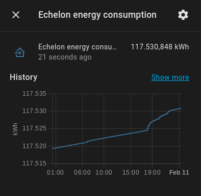
As it is the kWh counter it should be forever increasing. Little consumption will be slowly increasing, higher consumption will increase steeper.
When the problem appeared, it rose all of a sudden thousands of kWhs, and shortly after fell back to normal.
Due to the way I had defined the sensor in HA, this was a bigger issue than just that short glitch.
For it to be usable with the Energy dashboard it needs to have statistics collected each hour, and this requires a ‘state_class’ defined. For this kind of data it can be ‘total’ or ‘total_increasing’. To support meter reset the ‘total’ type requires a date specified where the meter was reset. Instead the ‘total_increasing’ type, which I had chosen, will see a decrease as a reset.
As the Energy dashboard works with the deltas, not only did the increase add thousands to the depicted consumption, when returning to normal it also added 117.000 kWhs because it assumed it was reset to zero and then consumed the reported value…
Gert had also noticed this at times, and had also mentioned it to me earlier. But in my rush to get something to show up I had also totally forgotten about it.
Rather than having to specify a reset date or risking negative consumption, I decided to continue with ‘total_increasing’. However, I did implement a limitation that would sanitize the kWh reading. If it increased more than 1000 Wh or decreased from the latest reading, it would discard the new value for up to an hour until finally accepting the new value if not returned to a more realistic value. It is only done in memory though, so not totally fail proof if HA is restarted during an issue, but it minimizes the risk.
A few days later Gert reported the issue had been found and firmware updated.
At the same time there was more info added to the webservice.
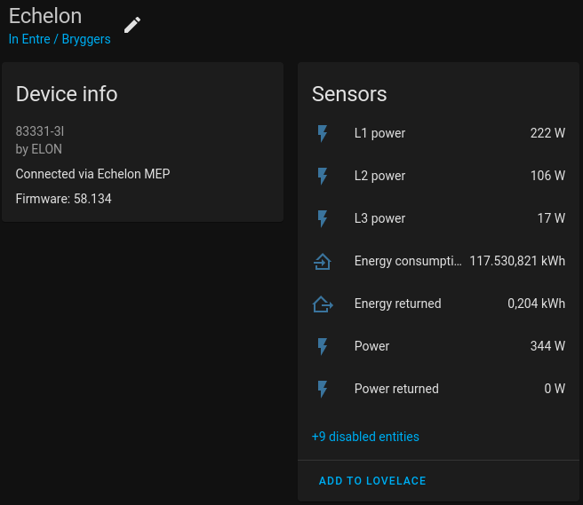
In a previous blog, it was shown that it could return info about itself like manufacturer, model and version. Although secondary, I find it nice and convincingly to have that reported as well.
Not only did the added info have metadata about the meter, it also turned out that similar data about the MEP module had been added.
In HA a device only has a predefined set of properties. So, how to depict both sets of device info?
Although not originally planned, it turned out simple enough, just make it appear as two devices. The meter itself and the MEP module:
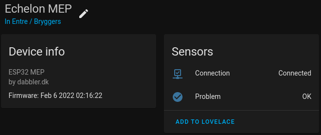
To do this, it requires at least one sensor on the MEP module. This is because it is the sensor that returns info about the device it is part of.
In this case I invented two binary_sensors that tell something about the status. One if the last http request succeeded, and two if the data returned doesn’t look as expected.
The “Connected via” relationship was new to me, and also something I wanted to try out… 😁 But it just worked, so no challenge in that.
As Gert and Graves had taken care of the difficult part, the most challenging part of this integration turned out to be the Configuration button, or as it is known internally the OptionsFlow.
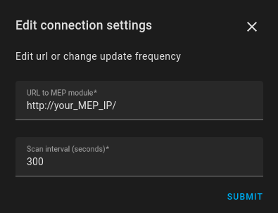
This I had not made with Min Volkswagen. The UI itself was not much different than the initial configuration, but I wanted it to be able to update the url to the MEP module and to change the scan interval (how frequently it polls the webservice).
The challenge with the url was that configuration and options are stored under different keys. And I didn’t like the idea of writing to both keys, and then making sure to read the right one if both were present.
Although I thought it would be a normal use case, I had to find a way to do it in a community thread where other developers had the same need.
Even worse when I wanted to make the scan interval configurable.
Gert had expressed concerns about the ESP32 being overloaded with requests, so I decided that polling it every 5 minutes would be sufficient for many use cases. In particular if the primary interest is the total kWh reading.
However, if you are interested in checking the power usage right now and want to see the difference when some device is on or off you need much more frequent updates.
Although you can buy plugs with the ability to report the consumption for a specific appliance, let’s also enable use cases that require readings from the meter almost as frequently as you might like for whatever purpose. When you have it in your own home and only polled by you, it is of much less risk of being overloaded than the module being exposed online right now.
HA has a really simple way for an integration to set a scan interval. It is a hardcoded value that I have not found a way to change dynamically. For integrations not using ConfigFlow and OptionsFlow it can be set in the configuration file, but making this apply requires a restart…
After studying other examples, I ended up disabling the built in triggering mechanism. Instead setting up a timer, that would fire an event to the sensors when it is time to update.
A change in the OptionsFlow dialog will reload the integration anyway, so although the timer is set up at load time it will update the timer interval when changed.
Besides the expected benefits, being able to reload the integration also turned out to have other advantages. Now it can unload the integration without restarting HA core, or enable and disable sensors without restarting. Just a much more convincing experience.
The integration is made publicly available for anyone to use. But to be usable in any way you will also need the hardware and not least the firmware, which currently awaits release from the NDA. So, continue to keep an eye on the blog for updates.
The integration can be found here: https://github.com/jnxxx/homeassistant-dabblerdk_powermeterreader
You will also see more screenshots in the README file.
Be aware that it does not contain any information about the MEP protocol. It just consumes the webservice provided by the ESP32 firmware, that is where the secret source is.
For ease of use and installation, I will try to get it into the HACS community listing of custom integrations.
The challenge will be if we can get a logo accepted, which is required. I already experienced once it is not so simple if you do not own the trademark rights. So, now we try to put it under the dabbler.dk name and logo.
Until included in HACS, you can add the url above as a repository to HACS yourself (as described in the installation instructions) and it will work just like it was. Only thing missing is the logo in the integrations overview.