
www.sommerhack.dk 2020 renewed our interest in communicating with our Echelon meter. During a session by Thomas Ljungberg Kristensen, WelcomeSecurity (https://www.welcomesecurity.net/) the different possibilities and the legislation was briefly covered and he inspired us to push harder to get some kind of access.
If you are following these posts, can read Danish and have a Smart Meter you would like to connect to – this page (created by Georg Sluyterman) might be of interest to you: BefriDinElmåler.dk.
As mentioned in the previous post we already started the process of getting further information from N1. The useable information was sparse and hidden in a lot of mis-information, but in hindsight we know that this was probably not on purpose, but simply because the N1 organisation and staff did not have the full picture of the solutions and/or simply did not know better. This simply seemed to be new to everyone involved…
N1 confirmed that the IR solution was encrypted and there were no way they could supply us the encryption key. Supposedly there were a hidden port behind a cover at the bottom of the meter, and we should purchase a “Izar / M-bus PCB” for it. We were a bit skeptical, but did find a hidden 6 pin interface in a plastic drawer on our meters… So it seems there were some truth to this…
N1 told us that a company called Develco had been involved in the developments, but had sold off the solution to an unknown 3rd party… Gert discussed a bit with N1 if they could claim that we could simply order this PCB, when it was nowhere to be found and they could not tell us where we could buy it… Is something REALLY for sale when you cannot buy it? 🙂
After researching this further Izar and M-Bus interfaces seemed to be a dead end… But researching “Develco”, hidden interfaces and solutions further we found this! (local copy of the PDF can be opened from here if the external link ever disappears)…
But wait a minute – this document does not mention “Izar” nor “M-Bus”!!! Insted new terms like “Multi-purpose Expansion Port (MEP)” and “ZigBee” is introduced. What the heck is a MEP port?
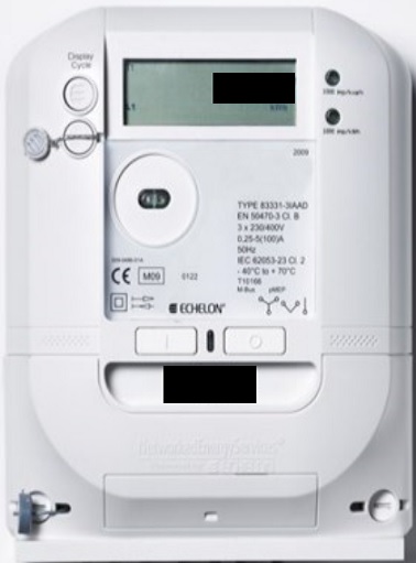
According to the document the Danish company Develco was actually involved in a project with EnergiMidt (parts of EnergiMidt are now N1) and NES (Networked Energy Services). And apparently as part of selling all these Echelon Type 83331-3IAAD (and similar model) meters in Denmark, a new plastic cover was developed providing access to the MEP screw terminals from a small “drawer” in the meter! It seems this solution is available for most (if not all) Echelon Type 83331-3IAAD (and similar model) meters in Denmark.
Unfortunately it was very hard to get in touch with Develco. We tried multiple times writing them, calling them etc. Finally Graves managed to convince a sales guy that we represented a company interested in purchasing SEVERAL PCBs to follow multiple plants power consumption more closely…. Only to discovere that the PCB never was produced as anything but a prototype / proof of concept… They would be happy to start production up for us , if we would only place an order of of 10,000 pieces or so…. Yet another dead-end…
The MEP “drawer” is well hidden. We did not know it was there before we found this document. As far as we know other tinkers investigating this also did not find it (or at least the few we spoken with afterwards didn’t know about it). This is simply a well hidden “secret” in plain sight. It looks like part of the cover, but it is actually a separate piece of the plastic you can pull out and it is prepared to receive a small PCB that connects to a 6 pin standard 2.54mm pin header. When you know it is there, it is obvious – we just didn’t notice it previously…
We tried to investigate the 6 pin interface, but it is hard when you have nothing communicating on it – and no idea what exactly to look for. If we could just open the sealed meter to reverse engineer – but that is illegal.
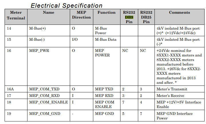
At least we found this in a manual forwarded to us (although it is marked CONFIDENTIAL), but it does not tell us how the pins are routed to the 6 pin header:
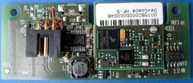
Inspired by Thomas – we pushed harder – and (we cannot reveal from where) “suddenly” we had a prototype of the so-called “Izar/M-Bus PCB”. This was really a breakthrough. We immediately tested it in a couple of Echelon meters, which immediately recognized it with a small “M” in the display. And according to the available documentation – that is the “icon” for a MEP device (Multi-purpose Expansion Port) and not a M-Bus device… So Izar/M-Bus appears to have been mis-information… This is in fact a MEP/ZigBee PCB…
Anyway – with a working PCB to reverse engineer and the above table, we soon found this pin-out of the “secret” 6 pin header (pins from top left to bottom right as seen when you look at them in the “secret” drawer in the meter:
- Pin 1: MEP_COM_GND (ground)
- Pin 2: MEP_COM_ENABLE (+5v or +12v on this pin will tell the meter to enable the interface)
- Pin 3: MEP_COM_RXD (meter serial receive pin)
- Pin 4: MEP_COM_TXD (meter serial transmit pin)
- Pin 5: MEP_PWR (+24/+26VDC power from meter. Note: This is max 1watt!)
- Pin 6: Not used / no connection
And also the above table confirms that MEP is a quite simple serial (RS232) based protocol.
Based on this we were soon able to capture communication with a small PCB between the meter and a couple of USB RS232/DB9 interfaces (like these)… We soon realized the serial communication parameters 9600,n,8,1 and to our surprise the protocol seemed binary and far more complex than expected…
During our early research we stumbled across this GitLab project. Looking at it, it seems MEP is a kind of clear text protocol with quite simple commands, but we soon realized this was another “rabbit hole” or we simply do not understand the code in the project. Anyway – it seems we cannot get any usable knowledge from that project.
We tried to research the protocol, but the only stuff we could find was that Echelon at some point sold training in this, and then references to this document “Echelon Corporation (2010c) MEP Device Developer’s Guide, Version 078-0372-01G, San Jose.”.
We also tried to reverse engineer it based on the recorded packages sent and received between the MEP/ZigBee module and the meter – but this was clearly outside our skillset. We had NO idea what was sent and received…
We were giving up after “hitting this wall” of the secret MEP protocol…
…and in our desperation we reached out to what we thought was the most unlikely party to help us (no, not N1) – stay tuned for our next post :-)…